boresight reference frame (BRF)

Standard

ECSS-E-ST-60-20C Rev. 2

Definition

reference frame where: - the origin of the Boresight Reference Frame (BRF) is defined unambiguously with reference to the mounting interface plane of the sensor Optical Head

Notes

  • NOTE 1 The X-axes and Y-axes of the BRF are defined to lie (nominally) in the plane of the detector perpendicular to the Z-axis, so as to form a right handed set with one axis nominally along the detector array row and the other nominally along the detector array column. Figure 3-3 schematically illustrates the definition of the BRF.
  • NOTE 2 The definition of the Boresight Reference Frame does not imply that it is fixed with respect to the Detector, but that it is fixed with respect to the combined detector and optical system.
  • NOTE In an ideally aligned opto-electrical system this results in a measured position at the centre of the detector. - the Z-axis of the BRF is defined to be anti-parallel to the direction of an incoming collimated light ray which is parallel to the optical axis - X-BRF-axis is in the plane spanned by Z-BRF-axis and the vector from the detector centre pointing along the positively counted detector rows, as the axis perpendicular to Z-BRF-axis. The Y-BRF-axis completes the right handed orthogonal system.
Glossary app image

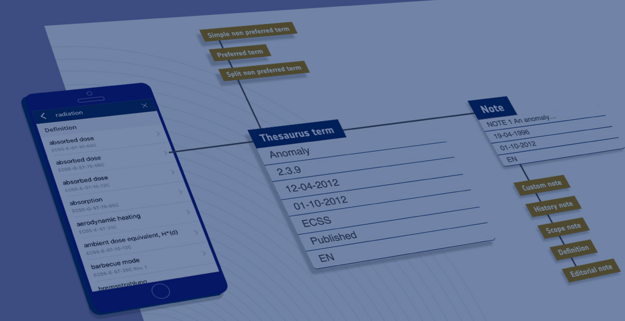
ECSS Glossary mobile applications

ECSS Glossary mobile apps available from iOS and Android store and ECSS Glossary Plugin for MS Word available from Microsoft Appstore
Search the online Glossary